Typical users of single-mode optical fibers are not concerned about the state of light polarization. Usually we think of single-mode fibers as guiding only one fundamental mode, not two modes with orthogonal polarization states. In fact, it is desirable to minimize polarization mode dispersion of standard single-mode fibers to reduce impulse spreading. In standard single-mode fibers, the output polarization is random and cannot be controlled. However, in certain applications it is necessary to maintain the polarization state of light as it passes through a fiber. Such systems include sensors, lasers, and fiber interferometers. Also, some devices and systems may exhibit different losses depending on light polarization, and operation on a controlled polarization state is necessary to keep the losses constant. When using such systems, standard single-mode fibers with poor polarization mode dispersion parameter are not enough and a different fiber structure is needed.
Polarization-maintaining fibers have an asymmetric structure that preserves the input state of light polarization. The polarization-maintaining behavior can be induced in various ways, the most popular one in commercial fibers being stress-inducing parts situated asymmetrically inside the fiber, as shown in Fig. 1. The figure shows Panda type fiber, which is convenient to use since its core diameter and numerical aperture are compatible with standard single-mode fibers.
During the fiber drawing process, the parts cool down and solidify at different temperatures. The induced stress causes the effective refractive index neff in Y direction to increase (see Fig. 1). Therefore, neff is different in Y and X directions. The refractive index difference is known as birefringence. If linearly polarized light is launched into a properly aligned fiber (so that the polarization axis is aligned with one of the fiber axes), the fiber will preserve the state of polarization of the signal. However, if the axes of light polarization and the fiber do not match, the fiber will not behave as a polarization maintaining fiber.
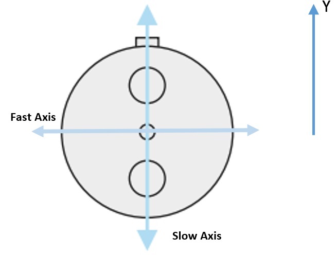
Fig. 1. Panda type of polarization maintaining fiber and its axes
Since the refractive index in Y direction is higher than in X direction, the speed of light polarized in this direction is smaller, and the Y axis is referred to as the slow axis of the fiber. The X axis is called the fast axis.
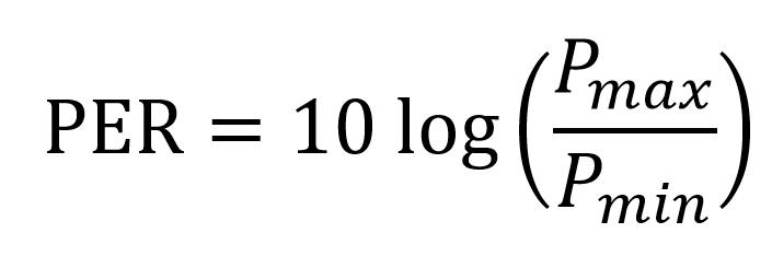
Using polarization maintaining fibers over the whole distance between the light source and detector is not enough to ensure controlled polarization state in the system. Aligning all system components is also extremely important. The parameter that gives information about optical power ratio of light polarized along a given axis is polarization extinction ratio (PER). The PER is defined as the ratio of the minimum and maximum output power of a given polarization.
Polarization extinction ratio measurement is based on measuring output optical power of a device or link as the angle of a polarizer placed behind it is changed. In an ideal case, linearly polarized light should be fully blocked by perpendicularly oriented polarizer. Minimum and maximum values expressed in decibels are then selected and subtracted. During measurements, a change of environmental conditions can influence the measurement results. Applying stress or changing the temperature leads to changes of birefringence. This can be an advantage when this effect is used to construct stress and temperature sensors, but causes signal distortions when measuring polarization state in other systems.
For this measurement, it is important to note what light source is used. When using a coherent light source with narrow line width, interference effects occur and the PER reading may differ depending on the induced stress if the fiber is misaligned and light is launched into both axes. If the output signals of the two different polarization states are in or out of phase, the total signal is linearly polarized, although the fiber is misaligned at the input. To prevent optimistic results, the fiber should be stressed (e.g. on a mandrel) while worst case measurement is being taken. Heating or cooling can also be used instead of stressing. Incoherent light source does not cause interference effects, but the results may be incorrect when a system intended for use with coherent light sources is measured.
PER can also be measured passively. Such measurement involves visual inspection of link components alignment. The PER value is then calculated from the alignment angle.
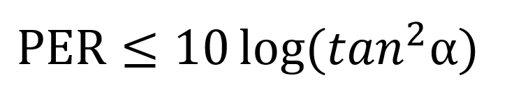
An alignment as close as possible to zero degrees should be achieved. For misalignments of two spliced or connected fiber axes by less than 1.8°, the PER has the value of 30 dB. Below this angle, the PER value drops to 20 dB for angles of about 6°.
The passive PER measurement method is often faster than the active one, but it has one crucial disadvantage. This method is mostly used for aligning optical connectors, which can induce stress in the fiber and change the polarization extinction ratio. Because of this stress, the geometrical axis is often different from the optical axis of the fiber in the connector. This difference can be as high as 2°, which is enough to critically change the difference between the measurement result and the actual PER.
Polarization maintaining patchcords and other devices are connectorized with PM connectors. These connectors can be adjusted in order to assure proper alignment of the connector key with the fiber axes. The connectors have an additional screw that allows turning the ferrule with fiber relatively to the connector body (Fig. 2a). The operation of adjusting the key to the fiber axes, or keying, is performed based on passive PER measurement using specialized equipment. Fig. 2b shows the front view of a PM connector during the keying process. The adjusted connectors are then glued to assure the alignment does not change as they are used. Slow axis keying is the standard in the market, but fast axis or 45 degree keying are also common depending on the application.
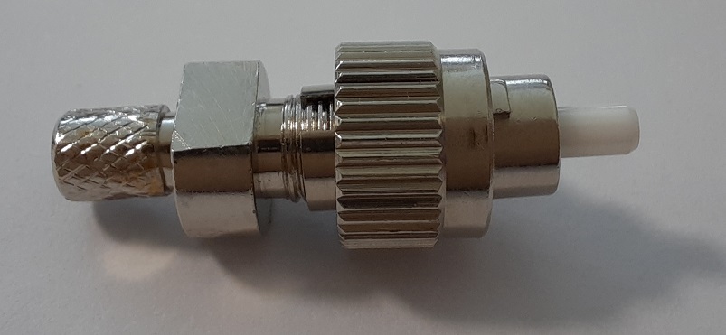
Fig. 2 Polarization maintaining connector.
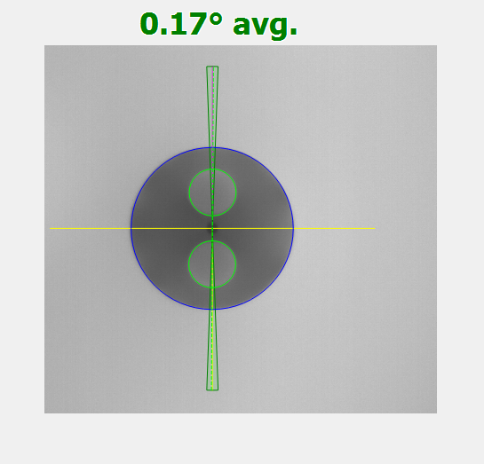
Fig. 3 Slow axis keying
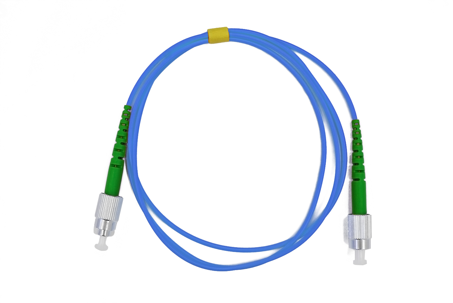
Fibrain offers PM patchcords terminated with FC/PC or FC/APC PM connectors optimized for operation in various spectral ranges. The connectors are made using high quality materials to assure reliable performance and low insertion loss. Each connector is keyed individually and PER values above 22 dB are guaranteed.